Featured

It begins!

I’m a little late in creating this blog, I get that. Honestly, I hesitated because I’m altering a car in a way that a purist of the brand would disapprove of. However as I talk about this project to others in passing it seems counterintuitive to share the same pictures and stories over and over; I may as well have a location dedicated to that.

So here it is.

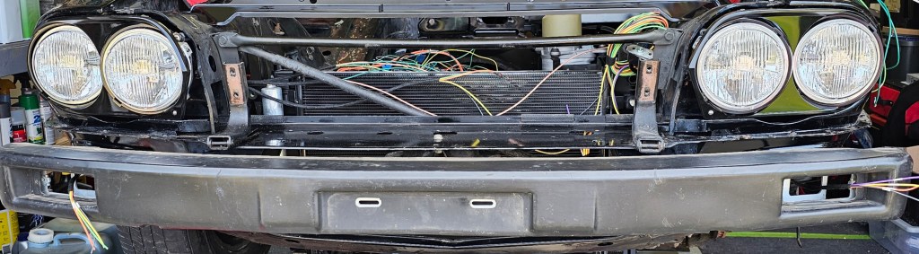
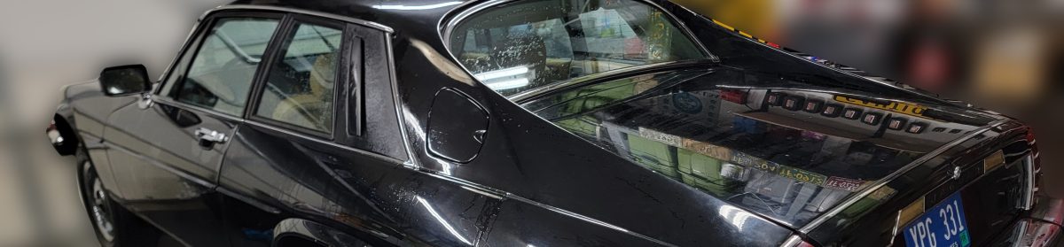
This is the journey of taking a 1986 Jaguar XJS and transforming it from a V12 gas thirsty mechanical beast to an electric cruiser.

“But Kris, that’s a V12, you can’t do that to a classic” Yeah. I can. Here’s the thing…this car hasn’t driven in over 15 years. I parked it once I discovered fuel was leaking out of the gas tank that was mounted IN THE TRUNK. And although it has been garaged this whole time, I’ve had issues with mice getting into the engine bay and doing mice things.

So, here’s an opportunity to take a vehicle that hasn’t seen the roads in a lifetime and make a nice Sunday cruiser out of it that doesn’t leak all the fluids.

I have comments disabled as I don’t want to deal with WordPress spam. Feel free to email me at kris (at) hainkm (dot) com.

Enjoy the journey.

Ut-Oh

(05/10/2026)

Update…! In the EV Conversions Reddit forum, a user said that this error is consistent with the resolver and that this would be an interesting failure. With that I decided to check the resolver impedance and it was fine.

i firmly reseated both cables and … It works! I think the large connector was maybe not set in all the way.

whew. Still leaving up the old post, just because. And here it is:

Well, a small setback.

Today when I was bench testing the motor again, I failed to connect the negative to the inverter control board and now the inverter thinks the motor is running at 16,383 RPM. Why this specific value? Well, 16,384 is 14bits, which is a typical bit resolution for an analog to digital converter.

I think I let some smoke out :/

Maybe, on the bright side, if the power part of the inverter is ok, I’ll upgrade to an Open Inverter board for some more power…

Motor stack is back together!

(05/08/2026)

I haven’t applied power yet, but the motor stack is back together, sealed and leak checked. I installed the high voltage inlet block from Inductive Autoworks and painted that black to match everything else.

Next step is to do one quick bench test to ensure everything still functions as it should, and then install it in the car for real!

Slowly becoming a car again

(05/02/2026)

I’ve had some pockets of time in the last month to get a few things going. First and foremost I was able to sandblast the motor and all of the brackets and then I decided to paint everything flat black. Most of this stuff you won’t even see, but the motor especially looks so much better.

I also got the new black headlight buckets installed and Holley Retrobright LED headlights. I cleaned up the Bosch fog/driving lamps and started replacing the halogen lamp with LED and rewiring those. I should have installation pictures of that in the next update.

Now an issue. I started installing a high voltage wiring block I picked up from Inductive Autoworks (https://inductiveauto.com/product/nissan-leaf-em57-inverter-dc-wiring-kit/) and I noticed that the plastic that holds the two copper terminals was sitting proud of the inverter top.

Apparently when the salvage yard removed the PDU from the top of the inverter stack, they must have assumed the HV side was maybe a plug? It’s not. It’s bolted in, and they used so much force that the entire glass fiber block was shattered.

I was able to straighten out the bent buss bars and made a quick 3D CAD model to replace what was broken. My version is a simplified setup compared to factory.

I made a number of trials in PLA to get the fit just right:

And then finally I made the end result in ASA, applied a tiny amount of blue Loctite to the bolts and called it a day. Next update I will have the motor stack put back together and the high voltage cables installed.

Motor is back out (for the last time?)

(04.05.2026)

Ok, I have the motor pulled and all the brackets out. Everything is ready for final weld, a light sandblast and clear coat and paint!

I also started fitting the radiator and condenser! This is from a 2016 Nissan Leaf, which is perfect because the motor is from….a 2016 Nissan Leaf! It actually fits really well and brackets will be simple(ish)!

Wheel Spin!

(03.22.2026)

Alright! I have had less than zero time to work on the car, but since the last time I posted I have actually made some major progress.

For starters, I have the rear trailing arms made and installed (although there is still more welding to do, then cleanup and paint) and I had a driveshaft made!!

Here’s a quick video showing the first move of the wheels! Ignore the driveshaft vibration, that has been corrected with an angle adjustment and both rear tires are pretty square.

Fitting the rear mounts

(01/14/2026)

The last two weeks I have worked on fitting the rear mounts for the motor cage. This involved making spacers (twice…erm, oops) for the belly pan plate and boring out a steel tube that will fit over the rubber mounts.

The next step is to weld up the back of the rear mounts, drill and tap some holes for sliders and fit it to the belly pan plate.

The motor is back in!

(12/29/2025)

I needed a way to easily get the motor on and off of my floor jack, or in and out of the cradle. Because of limited space and a sloping driveway, a traditional engine hoist/cherry picker wouldn’t work well.

So….I made this thing:

I was happy to see the motor, TorqueBox and cradle all weigh only 222.2lbs – – maybe that’s a lucky number now?

Once I had the motor assembly on the floor jack, I lifted it back into position and connected the front motor mount for the first official time.

Now the next step is to make spacers for the plate that goes where the transmission was (to clear the driveshaft) and fabricate the trailing arms. The PVC driveshaft placeholder fits exactly as it should.

Well, it’s been a while…

(12/23/2025)

It’s been nearly nine months since I’ve had the chance to work on the Jag. Just been a busy, busy year.

Anyway, where did we leave off? Oh, right, I welded up the motor carrier. So today I went to see if the motor fit in the carrier I welded up back in March. Spoiler: it did!

Next step is to get this on a transmission jack, hope it clears under the car with the transmission jack, and put in place to figure out where the rear motor mounts need to go.

After that, make a tailstock support and get a driveshaft made!

Until next time (and I promise it won’t be another 9 months…)

More motor mount work!

(02/23/2025)

I have all the parts cut, fitted, and tack welded for the front motor mount. Next step is to do the final welds, sandblast and paint. After that I will focus on a plate that needs to span over the driveshaft where the old transmission mount was, motor bucket and rear trailing arms.

It’s slowly coming together…

Quick update!

(02/16/2025)

This year has certainly started off extra busy and I haven’t had a lot of time since Christmas to work on the Jag.

A few things…

I got a PTC heater and CAN/LIN unit from EV Create (https://www.evcreate.com/volkswagen-air-ptc-heater-control-via-lin-bus/) in early January and an AC evaporator that should fit up to it nicely! I’ll be making a complete air box from scratch with servo-controlled dampers, so be on the look out for that in the future.

I have the start of the front motor mount underway, with some plates I had laser cut at SendCutSend along with a piece of 2″ square stock. I tack welded these and will pull it out of the car to do the final weld. I’m certainly not a welder, so this project will help me hone those skills.

Lastly I started making a cardboard template to draft what the bottom plate of the car will look like. This plate will mount under the driveshaft where the original transmission support mounted. This will then have two trailing arms that will support the back of the motor/gearbox “bucket”

HOPEFULLY by the end of March I’ll have the motor mounted in place and can start working on getting a proper driveline built and balanced.